There
are many ways to program the tool holders for automatic tool changes.
One method might not work as well as another on the different machines
which could use this system. Therefore, the method listed below is
for reference to demonstrate the theory of operation. It is
the users responsibility to input the correct values once the Tool
Changer
and Tool Pallet have been installed.
It is highly recommended that the power
switch to the Tool Changer be turned off till you are confident that the Tool
Pallet is setup correctly and the programming operates as intended.
It is recommended that you go through at least 10 cycles of picking up
and replacing all the tool holders before attempting automatic tool
changes while cutting parts. At the end of these directions there is a simple
program to cut the MRT Logo using a 1/4" and 1/8" bits. Also included are samples
of the VARIABLS.SBP file and the code used to pickup and replace a Tool
Holder. Since the directions will reference these programs, it is
recommended that you print out the programs so you can follow along.
Click on the buttons below to go to PDF versions of these files and
print them.
The programs have line numbers for easy
identification during the instructions. When using these files none of
these line numbers can be in the file. The highlighted lines in the program
are the lines you need to add to the cutting path program for automatic tool
changes.
This programming example assumes the Tool Pallet has been installed along
the left edge of the table along the Y-axis with the machine 0,0 in the
lower left hand corner. If your table is setup differently contact Technical
Support for different setup and execution files.
Defining
The Variables for VARIABLS.SBP
This programming method uses a
file to set the variables required to operate the system. This file is
called VARIABLS.SBP and is run during the
SETUP.SBP file which is run before any
program which utilize automatic tool changes. There are some variables which MUST be set by the
user before the system can be used.
Programming Files
Several files are required to operate the Tool Changer in addition to
the cutting file. The files that come with the Tool Changer need
to be placed in the location C:\ MRTPROG. If the files are placed
in a different location, some files may need to be changed to look in
the other location for the required files. The SETUP.SBP will be
used for every program which requires a tool change so it is recommended
that this file be assigned to a Custom Cut number so access is available
to this program from any folder.
Tool Holder Location
A file is included which will automatically find the center of the
Tool Holder when it is properly located in the Tool Bay. This file is called
TL-FINDV.SBP. The following steps are required to use this file:
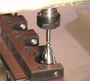
- Zero the machine at machine 0,0
- Insert a ¼ shaft into one of the Tool Holders.
This can be a broken ¼ shaft bit, a dowel pin or anything with a clean and
uniform circular end profile.
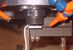
- Insert a Tool Holder in Tool Bay #1. Attach
the grounding wire with the two alligator clips from the bottom of the Tool
Holder to the grounding plate attached to your machine. The Tool Holder must
be oriented so that the anti-rotation slots are at a 45° angle to the Tool
Pallet.
- Manually load the Tool Holder with the 1/4" shaft into the Tool Changer
.
- Position the tool bit ~ ¼ above the center of the Tool Holder.
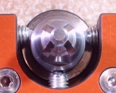
The program will find the top of the Tool Holder and then probe the
outside of the Tool Holder for 2 points on the Y-axis. The program
calculates the center of these points and probes 2 points on the X-axis
using the calculated Y value. The program saves the center points for Tool Holder #1. The
program pauses and prompts for the grounded Tool Holder to be moved to the next
Tool Bay. Hit any key to continue once the Tool Holder has been moved
. The process continues till all the Tool Bay centers have been
identified. The program then writes the centers to a file called TLPOSTN.SBP
which will be located in the directory where the SB.EXE file resides. Open
this file and copy the contents to the VARIABLS.SBP file in the locations requested in lines
24-39. (See the
Video Page for a demonstration of the
TL-FIND.SBP program)
&DELTAZEROPLATES
The next variable that needs assignment is &DELTAZEROPLATES. This is the difference between the zero plate when placed on the table top
to the zero plate on the Fixed Tool Holder. To find this value insert a Tool
Holder (without a tool bit is preferable) into the Tool Changer. Using your
zero plate, zero on the top of the table. Lift the Tool Changer and move it
to the center of the grounding plate on the Fixed Tool Pallet. Lower
the Tool Changer till contact is made with the zero plate. Record this value for
the &DELTAZEROPLATES in line 12 of
VARIABLS.SPB.
Zero Plate Thickness
Enter the thickness of your zero plate in line 19 of
VARIABLS.SBP for the
variable &ZEROPLATETHICK.
Fixed Tool Pallet Zero Plate
Center Location
 The next variables are the
X and Y locations of the center of the zero plate on
the Fixed Tool Platform. Make sure the machine is zeroed at the machine
0,0. Load a Tool Holder with a bit into the Tool Changer and move to the
approximate center of the zero plate on the Fixed Tool Platform. Record this
value and replace the numbers for the variables &XZEROLOCATION and
&YZEROLOCATION in lines 41 and 44. The previous variables need to
be defined only once. These variables are now stored to the VARIABLS.SBP
file.
The next variables are the
X and Y locations of the center of the zero plate on
the Fixed Tool Platform. Make sure the machine is zeroed at the machine
0,0. Load a Tool Holder with a bit into the Tool Changer and move to the
approximate center of the zero plate on the Fixed Tool Platform. Record this
value and replace the numbers for the variables &XZEROLOCATION and
&YZEROLOCATION in lines 41 and 44. The previous variables need to
be defined only once. These variables are now stored to the VARIABLS.SBP
file.
SETUP.SBP
The Z axis reference point for the MRT Tool Changer is the
bottom of the collet chuck with no Tool Holder installed. This is a stable
location and will not change so all measurements done in the Z axis must to
be done with no Tool Holder in the Tool Changer.
This programming method uses the home position or
machine 0,0 as a reference for the locations of the Tool Holders. If the
part you are cutting does not have its 0,0 point at the machine 0,0, the X
and Y offset of the local part 0,0 in relation to the machine 0,0, needs to
be programmed so the Tool Changer will be positioned correctly in order to
accomplish tool changes. This is done with the SETUP.SBP
program. This file is run just before any program requiring an
automatic tool change. Since this file will be used often, it is
recommended that it be assigned to a Custom Cut. This way access to this
file will be available from any directory. The SETUP.SBP program
operates as follows:
SETUP.SBP
- Line 4-6 - Set some variables
- Line 7 - Runs the VARIABLS.SBP file which sets the variables
required for automatic tool changes.
- Line 8 - Asks for user input for the X offset in relation to the
machine 0,0 for where the file will be cut.
- Line 9 - Asks for user input for the Y offset in relation to the
machine 0,0 for where the file will be cut.
- Lines10 - Jogs to the X, Y offset location
- Lines 11 -12 Asks user to put the zero plate under router. The
plate must be put on top of the part Z axis zero. This is
usually the top of the material or the top of the table.
- Line 14 - Instructs program to go the subroutine STOPRETURN on contact
with the zero plate
- Line 13 - 22 - Blows off the zero plate
- Line 14 - Lowers the router and goes to STOPRETURN on contact with
the zero plate
STOPRETURN
- Lines 56-60 - Lifts Tool Changer .25" and resets a slower Z axis
move speed
- Line 61 - Returns to the main program
SETUP.SBP
- Line 25 - Instructs program to go the subroutine SETZERO on contact
with the zero plate
- Line 27 - Lowers the Tool Changer till contact with zero
plate and goes to SETZERO subroutine
SETZERO
- Lines 67 - Zeros the Z value to the part 0,0
- Line 69 - Raises the Tool Changer to clear the Tool Pallet zero
plate
- Line 73 - Resets the Z axis move speed and returns to the main
program
SETUP.SBP
- Lines 30-31 - Jogs to the center of the Tool Pallet zero plate
- Line 69 - Raises the Tool Changer to clear the Tool Pallet zero
plate
- Line 73 - Resets the Z axis move speed and returns to the main
program
- Lines 32 - 43 - Makes contact with the zero plate, raises .25"
makes contact again and goes to the PLATFORMZERO subroutine
PLATFORMZERO
- Line 79 - Sets the ZEROPLATE variable to the distance between the
part Z zero and the Tool Pallet zero plate and returns to the main program
SETUP.SBP
- Line 48 - Lifts the Tool Changer up by 1/4"
- Line 49 - Jogs 6" in the +X direction to clear the Tool Pallet
The Tool Changer is now ready to cut a file with
automatic tool changes.
FP Command With The ,,,,,2
Offset Option
In this method of programming, the file with the tool paths is cut from
inside another file using the FP command with the ,,,,,2
2dD offset option.
This runs the cutting file using the part 0,0 instead of the machine 0,0.
Running the TESTPROG.SBP File
To cut the sample program, TESTPROG.SBP, a 12 x 12 piece of
material at least 1/4" thick must be secured to the table. A
1/4" bit must be loaded into a Tool Holder and placed in Tool Bay #1.
An 1/8" bit must be loaded into another Tool Holder and loaded into Tool Bay
#2. Run the OFFSETUP.SBP program to load the tool offsets for
at least these two tools. Run the SETUP.SBP program and enter
the approximate center of the 12"x12" board as the X and Y offset.
Place the zero plate on top of the 12"x12" piece of material as the top
surface was programmed as the Z axis zero and press any key to continue.
Once finished, run the TESTPROG.SBP and it will cut the file with a
tool change.
An explanation of the files follows:
End of program.